Mekanisme penarik teras lateral
Mekanisme teras lateral "lajur panduan cenderung gelangsar"
I. Klasifikasi mekanisme menaip dan teras-teras
Menurut ciri-ciri struktur, mekanisme penarik teras lateral diklasifikasikan ke dalam enam kategori utama berikut.
Mekanisme teras lateral "lajur panduan cenderung gelangsar".
2. Mekanisme penarik teras lateral "slider bent pin".
3. Mekanisme penarik teras lateral "blok slider T-slider".
4. Mekanisme teras-penarik lateral "silinder hidraulik slider".
5. Mekanisme teras teras bahagian atas.
6. Mekanisme penarik teras lateral slider cenderung.
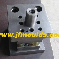
Dua: Bahagian sisi "Lajur Panduan Slider cenderung"
Reka Bentuk Lajur Panduan Terendai dan Panduan Kecenderungan Blok Tekanan Lajur

Pengilang acuan suntikan botol di China (JFMoulds.com)
Sudut condong a
Di bawah keadaan biasa, untuk a = 15 & deg; hingga 25 & deg;, sudut yang biasa digunakan adalah 18 & deg; dan 20 & deg; dalam julat ini. Yang lebih kecil adalah, lebih baik, kerana yang lebih kecil adalah, semakin kecil tork yang beruang lajur panduan yang cenderung, dan lebih kecil daya geseran yang beruang bahu gelangsar.
2. Apabila jarak teras yang menarik adalah kecil dan gelangsar agak tinggi, sudut kecenderungan. Nilai yang lebih kecil boleh diambil, tetapi minimum tidak boleh kurang daripada 10 & deg;. Apabila jarak teras yang menarik adalah besar, dimensi ketinggian gelangsar adalah kecil, dan daya pengapit bahagian plastik pada penarik teras lateral juga kecil, sudut kecenderungan. Nilai yang lebih besar boleh diambil, tetapi maksimum tidak boleh melebihi 30 & deg;
Saiz A bergantung pada jarak penarik teras lateral dan ketinggian gelangsar, dan bebas dari jarak pelepasan bahagian plastik. Secara umumnya, di bawah premis memenuhi keperluan jarak teras yang menarik, ketua lajur panduan cenderung harus sedekat mungkin ke permukaan bawah gelangsar. Sekiranya lajur panduan cenderung terlalu pendek dan kepalanya jauh dari permukaan bawah gelangsar, gelangsar akan tertakluk kepada tork yang agak besar semasa penarik teras. Tork ini akan meningkatkan geseran antara bahu gelangsar dan blok tekanan atau t-slot, dan sekurang-kurangnya, mempercepatkan memakai permukaan geseran. Dalam kes -kes yang teruk, ia boleh menyebabkan gelangsar "terjebak" dan menghalang teras daripada ditarik keluar. Oleh itu, pada peringkat awal penarik teras, panjang hubungan antara lajur panduan cenderung dan lubang gelangsar tidak sepatutnya kurang daripada dua pertiga daripada panjang lubang slider yang cenderung. Sebaliknya, jika pin panduan cenderung terlalu panjang dan perlu melangkaui permukaan bawah slider, kerana proses penarik teras diteruskan, disebabkan peningkatan panjang lengan tuil, tork yang ditanggung oleh pin panduan cenderung akan menjadi lebih besar dan lebih besar, akhirnya membawa kepada lentur dan ubah bentuk pin panduan yang cenderung. Sekiranya dimensi ketinggian gelangsar adalah kecil kerana jarak teras yang besar, kepala lajur panduan cenderung mesti melangkaui permukaan bawah gelangsar. Adalah disyorkan bahawa panjang lanjutan kurang daripada satu pertiga daripada panjang lubang slider yang cenderung.

(2) chamfer e di kepala lajur panduan cenderung
e hendaklah lebih besar daripada atau sama dengan sudut kecenderungan A lajur panduan cenderung untuk memastikan terdapat faktor keselamatan yang mencukupi apabila lajur panduan cenderung dimasukkan ke dalam lubang cenderung gelangsar. Apabila a & ge; 18 & deg;, kepala lajur panduan cenderung harus mengelakkan menjadi separa bulat sebanyak mungkin.
(3) Panjang l lajur panduan cenderung boleh dikira berdasarkan formula asas fungsi trigonometri: L = L1 L2 = S/SINA H/COSA
H ketebalan plat tetap; Jarak teras yang menarik; Sudut kecenderungan lajur panduan cenderung.
Tiga: Reka Bentuk Blok Tekanan Slider dan Slider
(1) bimbingan gelangsar
Titik berikut harus diperhatikan ketika merancang slider
Operasi slider harus lancar dan selamat, memastikan penarik teras lateral yang lancar tanpa sebarang jamming. Jurang dalam alur slaid harus seragam, tanpa sebarang kelonggaran atau ketegangan yang berlebihan. Toleransi yang sesuai antara gelangsar dan kerusi slaid ialah H7/F7.
2. Oil grooves should be provided on the sliding surface of the large slider, and there must be cooling water channels
When the sliding stroke of the slider is too long, the guide groove must be extended on the mold base. Generally, the length of the sliding part should be about 1.5 times the height. When extracting the core, the length of the slider beyond the mold frame should not exceed one quarter of the slider's length; otherwise, the guide slide groove should be added
Long.
4. The wedge block of the slider must be inserted into the lower die for locking, with an insertion depth of 10 to 20mm and a locking Angle of 5° to 10°.
The design considerations for the slider pressure plate are as follows.
The material of the pressure plate is 718.
2. Surface ammonia infiltration treatment.
3-edge chamfer C1.
4. Processing oil grooves on sliding mating surfaces.
5. Selection of the pressure plate
a. Standard specifications should be given priority for the pressure plate, followed by the "7" shape
B. The upper end face of the pressure plate should be as flush as possible with the template surface to ensure the mold's aesthetic appearance
c. The pressure plate should be avoided from being pressed simultaneously on the inner mold inserts and the template as much as possible.
d. To prevent deformation, the length of the pressure plate should be controlled under 200mm as much as possible.
(2) Positioning of the slider during mold closing
1. General requirements for positioning
A. The positioning surface should be selected as a plane.
B. The positioning surface should be selected on relatively fixed parts, such as moving and fixed mold inserts, mold bases, etc., and must not be selected on sliders and movable inserts
c. When the slider is used for relative positioning, the slope of the positioning surface should be more than 5° on one side
d. The positioning requirements for the fixed mold slider are high because wire clamping can affect the appearance of the plastic part, so more attention should be paid. The positioning method is basically the same as that of the moving mold slider.
2. For individual sliders, the sliders shown in (a), (B ), and (c) have good positioning effects.
3. For the Haff slider (also known as the split slider). The following points should be noted when designing.
A. Each slider must have a reliable positioning. Generally, it is positioned by inserts. In cases where inserts cannot be used for positioning, separate positioning blocks should be adopted for positioning.
B. It is strictly prohibited to directly position the Haff slider with circular cores, push rods, push tubes or small inserts (these parts are prone to deformation under force).
c. There must also be a process positioning block between the two sliders to ensure that the plastic part does not grade at the wire clamping point.
d. It is essential to ensure that the inner mold inserts have sufficient positioning strength in the sliding direction.
e. The slider is not precisely positioned by directly using the arc surface of the moving mold insert. Therefore, a positioning block must be added to the insert (the positioning block is inserted into the mold base).
Komoditi Mould_Taizhou Jiefeng acuan co, Ltd. (jfmoulds.com)
Maklumat Berkaitan
Penyelesaian untuk patah acuan dan rawatan kedutan udara
2025-08-08
Penyelesaian untuk fraktur acuan dan rawatan kerutan udara dari cetakan ...
Cara menyelesaikan masalah pemutihan, penyamaran dan ubah bentuk kedudukan tulang di saluran air acuan
2025-08-16
Cara Menyelesaikan Masalah Pemutihan, Menggoda dan Deformasi Bone Pos ...
Penyelesaian untuk serbuk getah dan calar sisi dalaman pada sprue acuan
2025-09-03
Penyelesaian untuk serbuk getah dan calar sisi dalaman pada sprue mol ...
Acuan suntikan: juara tersembunyi dalam pembuatan perindustrian
2025-07-14
Acuan suntikan: juara tersembunyi dalam pembuatan perindustrian di...
Bahagian plastik
2025-09-15
Bahagian plastik: Ketepatan dimensi plastik Partsthe ketepatan dimensi ...
Ekzos acuan (2)
2025-10-16
Ekzos Acuan (2) Satu: Masukkan Exhaustin rongga struktur berdinding nipis, akhir ...